


Guys (& Gals),
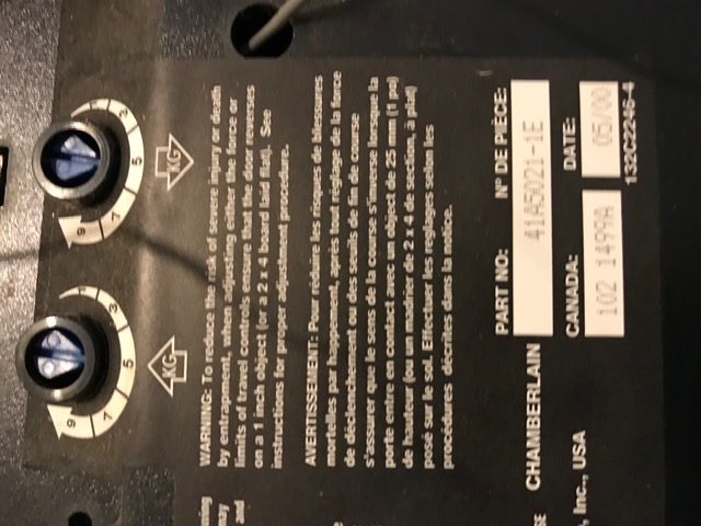
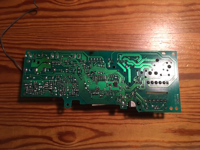
I am looking for a schematic diagram or other info for this logic board. I have attached pictures of the mounting cover and the front and back of the board for reference.
The problem I am having is that the opener operates with the remote but not with the wall switch. The wall switch is a door bell type. I have checked that it works properly (continuity opens and closes when activated) and that the wiring from the switch to the opener terminals is not open. I am also not getting any voltage at the wall switch terminals on the opener -- I assume I should get 12 or 24 V DC across the terminals?
The remote radio receiver is built into the board, not a separate/external module. I assume the remote closes the NO contacts of a relay when pressed, and the wall switch is wired in parallel to the NO contacts. Since the remote will activate the opener it would appear that most of the circuit board is good, there is some discontinuity between the terminals where the wall switch wires attach and the points on the board which activate the opener (which are also in parallel to the NO relay). This might be a broken circuit board trace or a bad solder joint, although I cannot see any.
So, here is where I need help:
1. Does someone have a schematic I could use to see exactly how the connections work? I suppose I could trace the connections but I really need to confirm what I get.
2. There are 3 relays on the board. Which is the one activated by the remote, what are the other 2? One is white, 2 are black.
3. There is a single connector on the board with 11 pins (grouped 4, 2, 5), does someone have the usage of each pin? Fo example I assume 2 are for the 120 Volts AC power, others go to the motor, the light bulb etc.
Any other suggestions on what might be wrong or how to troubleshoot?
Thanks a lot in advance.
» Where is the microphone in iPhone 11?
» Craftsman Opener having issues
» How to Side Swipe On Instagram?
» QR code menu
» Enhancing the quality, accuracy, and compliance of Wikipedia articles
» How can this possibly happen??
» What is garage door repair long island?
» How to Clean and Maintain Your Mobile Cover for Longevity