


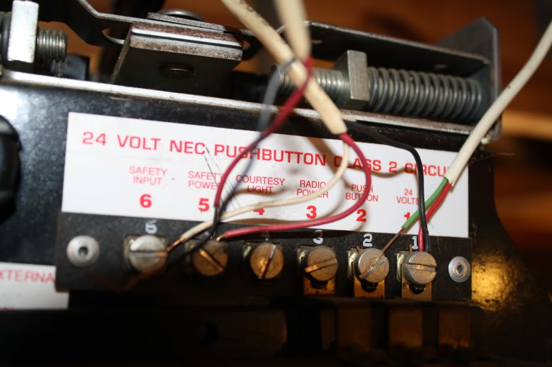
There are two (2) wires going from the circuit board to the infrared sensor(s). One (1) is a 3-wire (red, black & white) and the other is a 2-wire (red & black). The 2-wire got caught up in the chain and had to be repaired. I can't figure out where the black wire should connect. The red wire is connected to the Safety Power (5). The other options are Safety Input (6), Courtesy Light (4), Radio Power (3), Push Button (2) and 24 Volts (1). Which of these should the black wire be attached to?

» Craftsman Opener having issues
» Sell My House Fast Phoenix
» MOTTIFY EU
» Where is best place to buy torsion shafts locally?
» Sears Door Sensors Won't Align
» Garage door spring repair
» Where is the microphone in iPhone 11?
» How to Side Swipe On Instagram?